Home » Without Label » Ac Battery Wiring Diagram - Battery Charger Ac Adapter Wiring Diagram Electric Power Usb Charger Electronics Electrical Wires Cable Png Pngegg : Below you will find the most standard rv inverter wiring diagram.
Ac Battery Wiring Diagram - Battery Charger Ac Adapter Wiring Diagram Electric Power Usb Charger Electronics Electrical Wires Cable Png Pngegg : Below you will find the most standard rv inverter wiring diagram.
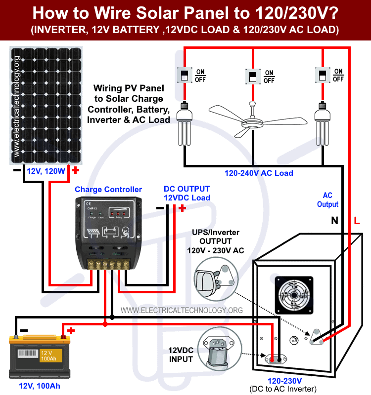
Ac Battery Wiring Diagram - Battery Charger Ac Adapter Wiring Diagram Electric Power Usb Charger Electronics Electrical Wires Cable Png Pngegg : Below you will find the most standard rv inverter wiring diagram.. The drawings do not replace the large single electrical diagrams available from the club stores and vendors, they work in conjunction with the large diagram. So once again, we need an inverter to switch the dc power from the battery into ac power for the home. I allows your house and start battery to remain isolated except for emergency conditions. A 2 kw, 4 kw, and 8 kw system are shown and include the solar panels, combiner boxes, charge controller (s), power inverter (s), battery bank, shunt & meter circuits, ac breaker panel, and ac generator wiring. Dc load is also connected to the dc output terminal of the charge controller.
The most common components are capacitor, resistor, and battery. Manual wiring diagram and parts list for specific models. However, before getting to work, we recommend you the following essential tips for installing an rv inverter: Proper battery management, including switching and charging, is essential for safe and reliable operation. The following solar panel wiring diagram shows that an 120w, 12v solar panel is directly connected to the 12v charge controller.
How To Wire Solar Panel To 120 230v Ac Load And Inverter from www.electricaltechnology.org Our autonomy and comfort depend a lot on the electrical system of our diy camper van conversion. Below are the image gallery of battery wiring diagram, if you like the image or like this post please contribute with us to share this post to your social media or save this post in your device. There are also other elements like ground, switch, motor, and inductor. I allows your house and start battery to remain isolated except for emergency conditions. Popular ebook you must read is club car ds battery wiring diagram. The electronic timer kit is powered by the battery and/or the ac line voltage and will not operate unless powered by the proper dc battery voltage and polarity and/or ac line voltage. The drawings do not replace the large single electrical diagrams available from the club stores and vendors, they work in conjunction with the large diagram. However, before getting to work, we recommend you the following essential tips for installing an rv inverter:
A double pole on/off/combine battery switch (like this one) is a great choice for a single engine, two battery boat wiring system.
The green ground wire in the ac input wiring must be connected to the charger ground stud identified by a green dot and ground symbol. I go over 4 ac condenser wiring diagrams and explain how to read them and what a. Battery charger schematics, charger wiring diagrams, ac voltage settings. Always put a fuse between the battery and the power inverter, so that if a short circuit occurs, the fuse protects the installation. So once again, we need an inverter to switch the dc power from the battery into ac power for the home. I have made several changes over the years. Ac battery wiring diagram / 1. Popular ebook you must read is club car ds battery wiring diagram. Proper battery management, including switching and charging, is essential for safe and reliable operation. The electrical diagrams on this page were researched and drawn by bill taylor and they show the detail of one electrical system at a time. The following diagrams explain how activation of the emergency lighting is achieved, using the main types of central battery systems. We've changed the diagram a bit now to show the start battery running through our new marine battery switch. The following solar panel wiring diagram shows that an 120w, 12v solar panel is directly connected to the 12v charge controller.
However, before getting to work, we recommend you the following essential tips for installing an rv inverter: A 2 kw, 4 kw, and 8 kw system are shown and include the solar panels, combiner boxes, charge controller (s), power inverter (s), battery bank, shunt & meter circuits, ac breaker panel, and ac generator wiring. Always put a fuse between the battery and the power inverter, so that if a short circuit occurs, the fuse protects the installation. We've changed the diagram a bit now to show the start battery running through our new marine battery switch. Every symbol that's shown on the diagram reveals specific circuit element.
68 Camaro Ac Wire Diagram Wiring Diagrams Fate Dare from static-resources.imageservice.cloud We've changed the diagram a bit now to show the start battery running through our new marine battery switch. As stated earlier, the traces in a monaco rv wiring diagram represents wires. I go over 4 ac condenser wiring diagrams and explain how to read them and what a. These systems are also common in rvs which meshes with a project i'm currently gearing up for. Please choose a year from the menu at left to start your search. For one, i've installed an inverter and smart charger, both of which require heavy gauge wiring to the house batteries. Unlike solar inverters, battery inverters also need to be able to take ac power from the home, turn it into dc and store it in the battery. These example system diagrams will show how to connect the components of a solar energy system.
A battery inverter is a similar device to your solar inverter.
I go over 4 ac condenser wiring diagrams and explain how to read them and what a. These systems are also common in rvs which meshes with a project i'm currently gearing up for. A wiring diagram is a streamlined conventional pictorial depiction of an electric circuit. Proper battery management, including switching and charging, is essential for safe and reliable operation. Ac − o f7b−0.8 battery + g01 battery s036b switch, push button start a b spf7d aa:0 a frc1_p1 key sw crank starter ign rh oper a17 control unit, vecu (vehicle ecu) a6 b28a14 b13 frc3:e86 x2d10−0.8 spx2d x10_c1 cb28−0.8 frc3:e30 relay, start cntl 1 rly36 85 86 30 87a 87 frc3:e87 pbstart:b. Ac battery wiring diagram : For one, i've installed an inverter and smart charger, both of which require heavy gauge wiring to the house batteries. As stated earlier, the traces in a monaco rv wiring diagram represents wires. Above is a diagram of my 12 volt wiring as it is right now in 2020. I have made several changes over the years. The electrical diagrams on this page were researched and drawn by bill taylor and they show the detail of one electrical system at a time. The electronic timer kit is powered by the battery and/or the ac line voltage and will not operate unless powered by the proper dc battery voltage and polarity and/or ac line voltage. The following diagrams explain how activation of the emergency lighting is achieved, using the main types of central battery systems.
Battery and inverter are connected to the battery terminals (positive & negative) of the charge controller. A double pole on/off/combine battery switch (like this one) is a great choice for a single engine, two battery boat wiring system. The green ground wire in the ac input wiring must be connected to the charger ground stud identified by a green dot and ground symbol. Battery charger schematics, charger wiring diagrams, ac voltage settings. We've changed the diagram a bit now to show the start battery running through our new marine battery switch.
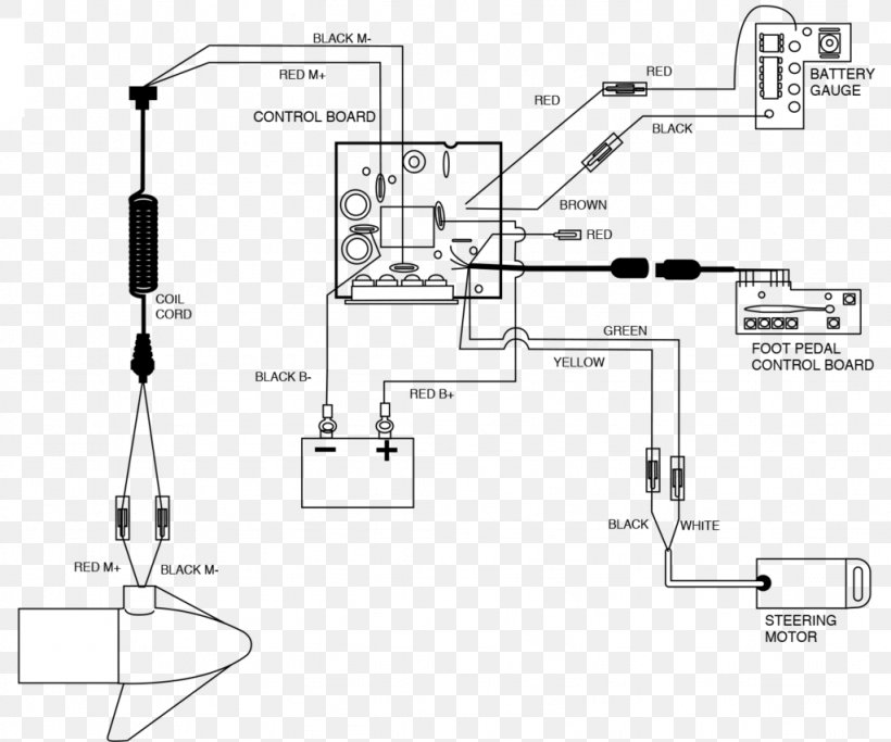
Battery Charger Wiring Diagram Trolling Motor Electric Motor Png 1024x854px Battery Charger Ac Power Plugs And from img.favpng.com Otherwise, the arrangement won't work as it should be. Below is a rv electric wiring diagram or schematic including the converter and inverter for a generic rv. No power means no fridge, no lights, no smartphone = no instagram = no #vanlife as we know it therefore, we want our electrical system to be safe, reliable, and to work from the first time; These systems are also common in rvs which meshes with a project i'm currently gearing up for. A double pole on/off/combine battery switch (like this one) is a great choice for a single engine, two battery boat wiring system. Each part ought to be placed and connected with different parts in specific way. Those parts are included in theservice. Find instructions, manuals and troubleshooting help.
I have made several changes over the years.
Above is a diagram of my 12 volt wiring as it is right now in 2020. Camper trailer battery wiring diagram | trailer wiring diagram. Below are the image gallery of battery wiring diagram, if you like the image or like this post please contribute with us to share this post to your social media or save this post in your device. Everything depends on circuit that is being constructed. Ac battery wiring diagram / 1. Each part ought to be placed and connected with different parts in specific way. A wiring diagram is a streamlined conventional pictorial depiction of an electric circuit. Always put a fuse between the battery and the power inverter, so that if a short circuit occurs, the fuse protects the installation. We've changed the diagram a bit now to show the start battery running through our new marine battery switch. How to read ac or air conditioner condenser unit wiring diagram / schematic. These example system diagrams will show how to connect the components of a solar energy system. Proper battery management, including switching and charging, is essential for safe and reliable operation. Those parts are included in theservice.